Structural principle
General current transformer structure principle: The structure of the current transformer is relatively simple, consisting of primary windings, secondary windings, iron cores, and structures, housings, and terminals. The working principle is basically the same as that of the transformer. The number of turns (N1) of the primary winding is less, directly connected in series with the power line. When the primary load current () passes through the primary winding, the alternating magnetic flux is generated to produce a proportionally reduced Secondary current (); the number of turns of the secondary winding (N2) is large, and the secondary load (Z) of the current coil of the instrument, relay, transmitter, etc. is connected in series to form a closed loop, since the primary winding is equal to the secondary winding. Ampere number, I1N1=I2N2, the rated current of the current transformer is smaller than that of the current transformer. The secondary winding is close to the short-circuit state, which is equivalent to a short-circuited transformer.
The feedthrough type current transformer has no primary winding in its own structure, and the current carrying (load current) wire acts as a primary winding from L1 to L2 through a circular (or other shape) core made of silicon steel sheet coil. The secondary winding is directly and evenly wound on the circular core, and forms a closed loop in series with the secondary load of the current coil of the meter, the relay, the transmitter, etc., since the through-current current transformer does not have the primary winding, the ratio is based on one time. The number of turns in the core of the transformer is determined by the number of turns in the core of the transformer. The more the number of passes, the smaller the ratio is. Conversely, the fewer the number of passes, the larger the ratio, the rated current ratio: I1 in the formula额定 一次 once rated current; n —— 穿 匝.
Multi-tap current transformer. This type of current transformer has the same primary winding. When winding the secondary winding, several taps are added to obtain a plurality of different ratios. The utility model has a core and a primary winding with a fixed number of turns. The secondary winding is wound on the insulating cylinder which is set on the iron core by an insulated copper wire, and the secondary winding taps of different ratios are taken out and connected to the terminal block. Each tap is provided with its own terminal block, thus forming a plurality of ratios. The advantage of this current transformer is that the wiring of the secondary terminal can be changed according to the load current ratio, and the ratio is changed without replacing the current. Transformers provide convenience for use.
Different ratio current transformers. This type of current transformer has the same core and primary winding, while the secondary winding is divided into two windings with different turns and independent windings to meet the needs of different ratios and different accuracy levels under the same load current. For example, in the case of the same load, in order to ensure accurate measurement of electric energy, the requirement is relatively small (to meet the load current of about 2/3 of the rated value), and the accuracy level is higher (for example, 1K1.1K2 is 200/5.0. Level 2); and the relay protection of the electrical equipment, considering the protection factor of the fault current is larger, the requirement is larger, and the accuracy level can be slightly lower (for example, 2K1.2K2 is 300/5.1).
Primary winding adjustable, secondary multi-winding current transformer. This type of current transformer is characterized by a variable ratio range and can be changed, which is more common in high-voltage current transformers. The primary winding is divided into two sections, which respectively pass through the core of the transformer, and the secondary winding is divided into two independent windings with taps and different accuracy levels. The primary winding is connected to the connecting piece of the device outside the transformer. By changing the position of the connecting piece, the primary winding is formed into a series or parallel connection, thereby changing the number of turns of the primary winding to obtain different ratios. The secondary winding with tap is divided into two windings with different ratios and different accuracy levels. As the position of the primary winding tab changes, the number of turns of the primary winding changes accordingly, and the ratio changes accordingly, thus forming A multi-range ratio. The different ratios and different accuracy levels of the secondary independent windings with taps can be applied to energy metering, indicating instruments, transmitters, relay protection, etc., respectively, to meet different usage requirements.
Combined current and voltage transformer. The combined transformer is composed of a current transformer and a voltage transformer, and is installed in a high-voltage metering box and a cabinet, and is used as a power source for measuring electric energy or using a relay protection device for an electric device. The combined current-voltage transformer is to fix the primary and secondary windings of the two or three current transformers, the primary and secondary windings of the iron core and the voltage transformer, and the iron core to the steel body frame, and is immersed in the transformer oil. In the box body, the first and second winding outlets are led out and connected to the high and low pressure porcelain bottles outside the box to form an insulated and closed whole. The primary side is connected to the power supply line, and the secondary side is connected to the metering device or the relay protection device. According to different needs, the combined current and voltage transformer is divided into V/V wiring and Y/Y wiring to measure the electric energy when the three-phase load is balanced or unbalanced.
Error measurement
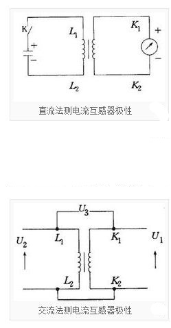
Direct current method
Use 1.5~3V dry battery to connect the positive pole to the primary coil L1 of the transformer. L2 is connected to the negative pole. The secondary side K1 of the transformer is connected to the positive electrode of the milliampere meter, and the negative pole is connected to K2. After the wire is connected, the K is closed. The pointer is positively biased. After the pull-off, the pointer of the milliampere meter is negatively biased, indicating that the end of the transformer connected to the positive pole of the battery is of the same polarity as the end connected to the positive end of the milliampere meter.
1. K1 is the same polarity, that is, the transformer is depolarized. If the pointer swings opposite to the above, the polarity is added.
Communication method
The amount of compensation is as follows:
Δf=Nx/(N2-Nx)×100%
Number of compensation
Only the contrast difference acts as a compensation, and the compensation amount is independent of the secondary load and current magnitude. The number of compensation parameters is generally only a few, and the compensation for the number of turns should be calculated when the secondary impedance of the current low terminal is maximum, and the error of the secondary impedance of the current high terminal is the smallest. For high-precision miniature current transformers, if the compensation is only 1 匝, it will compensate for the excess. At this time, half-turn or fractional 匝 compensation can be used. However, the number of turns of the current transformer is calculated by the closed loop through the core window, and the number of turns of the current transformer is calculated one by one, and there is no such case. For the use of semi-turn or fractional enthalpy compensation, auxiliary means such as: double winding, double iron core, etc. must be used. The auxiliary core compensation contrast and angular difference play a compensating role, but the method of assisting the core compensation is more complicated. For capacitor compensation, the capacitor can be connected directly across the secondary winding. The contrast difference is positive compensation, the compensation size is proportional to the X component of the secondary load Z=RiX, and proportional to the compensation capacitor size; the diagonal difference is negatively compensated, the compensation magnitude and the secondary load Z=RiX The component is proportional to the compensation capacitor size. Capacitance compensation is an ideal compensation method. In the miniature precision current transformer, the current/voltage conversion of the secondary winding directly connected to the operational amplifier has a secondary impedance of substantially zero, and the effect of the capacitance compensation is relatively small. Generally, the phase shift circuit can be added in the current/voltage conversion stage to solve the angular difference problem. The user can adjust and calculate the phase shifting circuit according to the test error data in the test report of the transformer of the current transformer when it is shipped from the factory.
 Chinese
 English